Week Ten
Click the Arrow to Proceed to Project Page
Click the Arrow to Proceed to Project Page
Using a Proximity Sensor
This week we were tasked with designing a board and connecting a sensor to a microcontroller to measure something. I am trying to start working towards the final nap/meditation/productivity pod, so I tried to think about devices that might be useful to incorporate. One of the challenges I have been thinking about is how potential users can determine if the nap pod is in use without disrupting the person currently inside. So, using my (newly) established circuit-designing skills, I decided to use a proximity sensor that I may eventually be able to use to determine if someone is walking up to the pod. Next week I will work on coding the RGB LED to flash different colors depending on the distance that the user is from the pod.
Board Design
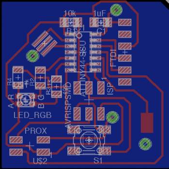
Once again, I used Eagle to design a board. I spent a long time looking for the proximity sensor piece to add to my board before realizing that all I needed was a 4 pin (2X2 SMD) connector to externally connect the sensor. I placed a resonator in the circuit as the distance for the sensor is measured based on the time it takes the ultrasonic signal to be sent out (by the “trigger” side), bounced back, and received (by the “echo” side), so I didn’t want to rely on the internal clock of the ATTiny. I used the ATTiny 84 instead of the 44 so that the microcontroller would have greater memory. I added an RGB LED and a pushbutton for testing purposes (and for later use for an output device). I mostly used autoroute to place the traces, whereas last time I had opted to route by hand. I found autoroute mostly worked.

Ermal taught me how to design a board to have two layers, so the bottom plane acts as a ground layer. This really helped me make a clean, easy to route board. I had to use vias to achieve this. He also showed me how to write a script to export my board into multiple pngs to represent relevant sets of layers for milling. You essentially look at the number of the layers you want to show and do the following:
SET PALETTE BLACK ( use this to make the background black)
WINDOW;
DISPLAY NONE (start by hiding all layers)
DISPLAY 1 17 18 (select the layers you want to show)
EXPORT IMAGE ~/pcb_top.png MONOCHROME 2000 (export, the name, monochrome setting, and dpi)
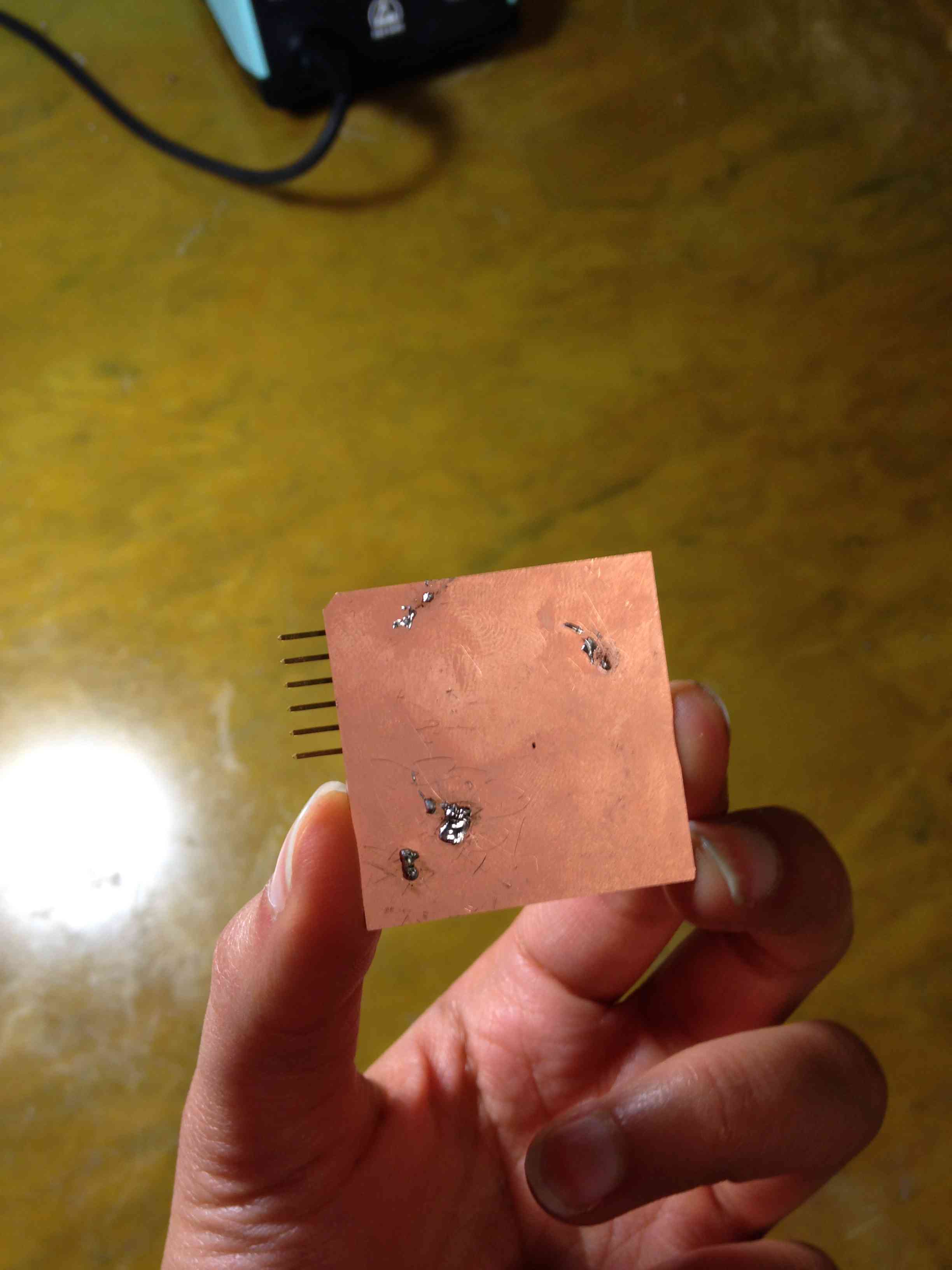
This really helped expedite the process. We used double-sided copper to mill the board (see my previous electronics week pages to learn more about milling). We had to cut deeper than expected to release the board (probably because both sides were copper).
Assembly and Programming
Soldering was relatively simple – Ermal taught me to put solder down on the corner pad of all components before placing the components, and then just heat the solder up when I wanted to place the component. This really helped me (previously I had felt like I needed extra sets of hands to get everything to work). The one interesting thing to note is that to establish the back plane as ground, you have to use wires to connect the front and back planes (place them through the holes, solder the tip to the top level, clip the wire to be as flush with the back layer as possible, and solder it there). Use a multimeter afterwards to make sure that all points are connected.

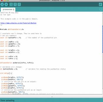
This week I decided to use the Arduino IDE instead of the terminal and makefile method. It turned out to be way, way simpler, especially since Arduino has a wealth of resources available online. I started by loading the bootloader specific to my board.


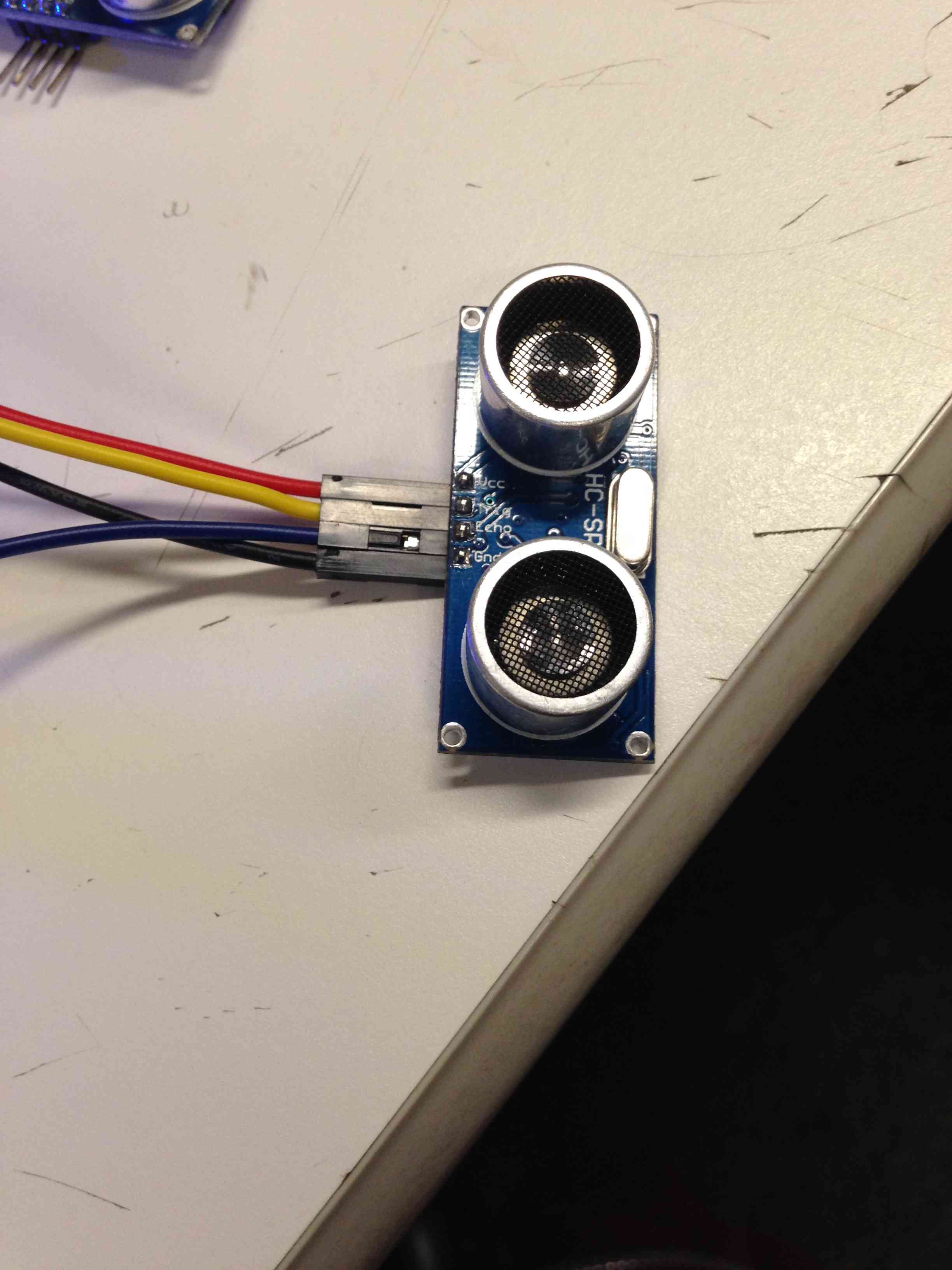
Using the high low tech tutorial that I cited in Week 6, I determined which pins to use in the arduino code. For my piece, the Trigger was Pin 6, and the Echo was pin 2. I used female to female wires to connect the sensor to my 2 x 2 SMD connector. To get started, I had to employ the Software Serial functionality of Arduino. The SoftwareSerial library allows serial communication on other digital pins of the Arduino. I set up the Rx pin as 0 and the Tx pin as 1 to send a receive info. I used the online arduino tutorials (such as this one) to set up a code for this process. (The essence of this process is setting up the necessary inputs and output pins, setting the trigger pin as low, then high, and then low with delays in between, and setting the echo as high afterwards to read the input). There is a conversion factor (29.1) to get from duration to distance based on the speed of the ultrasonic wave.
I later found out I had to download a patch to fix the linker (which runs after the compiler) as originally the IDE was struggling to send large files (over 4 KB) to the board. I found this patch by googling the error.
Initially, the board just read zeros when I opened the serial monitor. I changed the clock to the external resonator, and I swapped out the sensor. It worked!

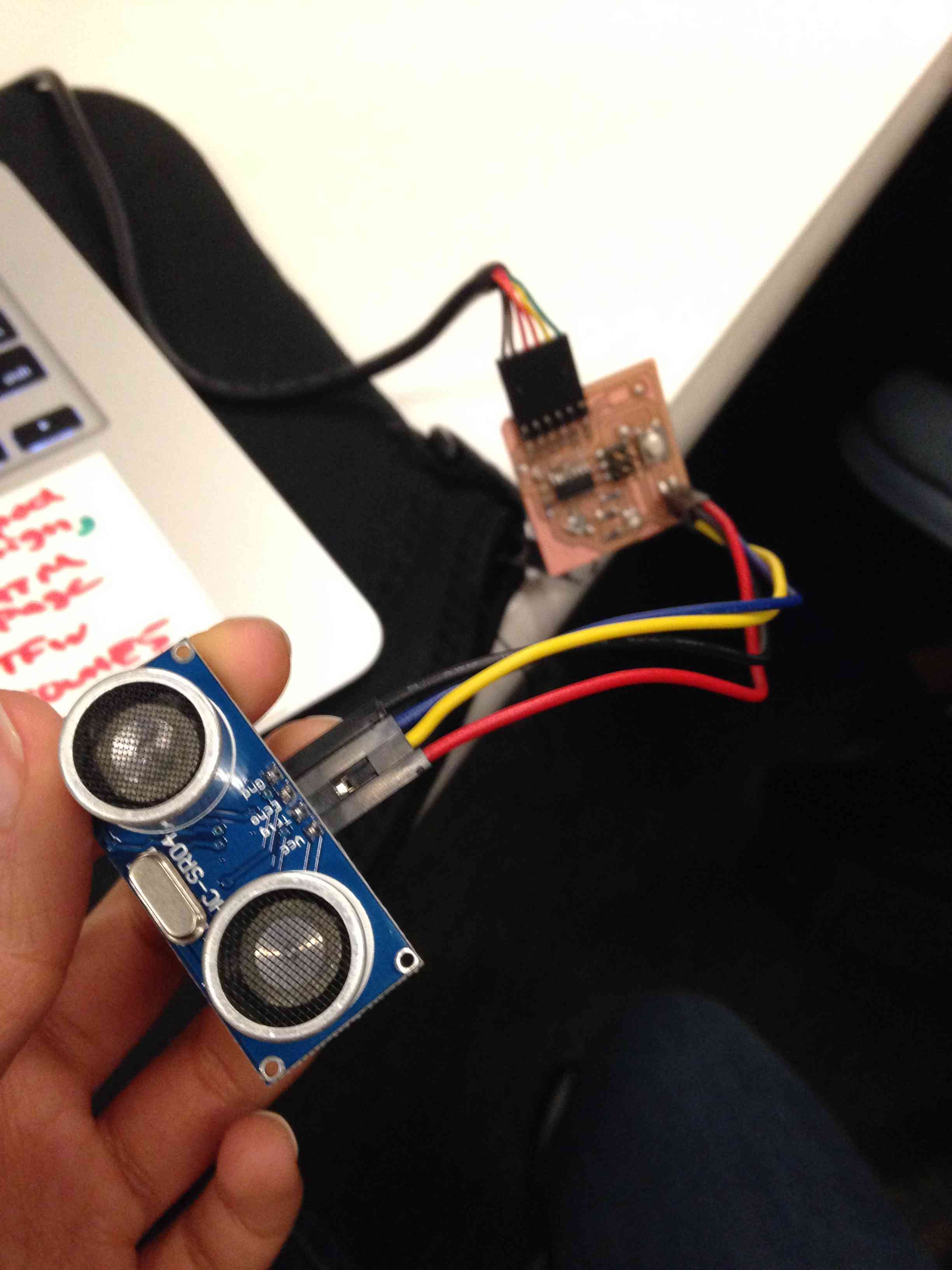

Here in this last image you can see the sensor reading the distance as I put my hand close and then pulled it away.
Connecting the input to an output
Since I had already incorporated an RGB LED last week, adding an output to my system was really simple. I added a few lines to my Arduino sketch as shown below:
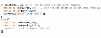
This set the LED such that green would flash when an object was far away, and blue would flash when an object got closer.
I recorded the device in action here. As my hand approaches the sensor, the color changes. Jonathan pointed out something that had been bothering me - the colors seemed to be reversed. When my hand gets closer, the green light turns on, and when I pull it away, it turns blue! (Also the red is on the whole time, so all of the colors are slightly off). Jonathan told me that at very close ranges, the sensor reads the distance as if the object was actually really far away, so this explains why the blue light engages at intermediate distances and the green light engages at far or very near distances.
Currently, the Red LED is connected to the same microcontroller pin as the echo function. I might redesign the board to fix this. I think to implement this on my final project, I would want to enclose the circuit in a case that amplified the signal (perhaps an "in use" sign box or something).
Thanks to Alexis, Juliana C, Juliana N, Palash, John and Tom for their help, support, and advice :). Thanks to Ermal for walking me through this process and helping me debug so many steps of the assembly and programming!